Model LV-14 MKII TourLed IPEdition EN · 04 / 2026 · V1Dokument-Nr. LV14-EN-01
IP65 LED Par · RGBW 4-in-1
LV-14 MKII
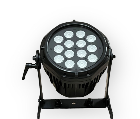
Weatherproof tour par with 14 × 8 W RGBW 4-in-1 LEDs, seven DMX personalities, ID addressing for up to 66 fixtures per DMX address and frost filter
Operating manual. Please read in full before first use and keep for future reference.
Light source
14 × 8 WRGBW 4-in-1
Beam angle
15°+ frost filter
DMX channels
3–117 personalities
IP rating
IP65Outdoor
Lexvision LV-14 MKII TourLed IPForeword · About this document
Foreword
00Welcome
Thank you for purchasing the Lexvision LV-14 MKII LED PAR. Every fixture has been thoroughly tested and has been transported in perfect operating condition.
Carefully check the carton for damage that may have occurred during transport. If the carton appears damaged, carefully inspect the fixture for any damage and be sure all accessories necessary to operate the unit have arrived intact. Carefully unpack the carton and check the contents to ensure that all parts are present and have been received in good condition.
0.1AC Power
This fixture has an auto-switching power supply that accommodates a wide range of input voltages from 100 V to 240 V AC, 50–60 Hz. The only thing necessary before powering on the unit is to make sure the line voltage applied is within the range of accepted voltages. All fixtures must be powered directly off a switched circuit and cannot be run off a rheostat (variable resistor) or dimmer circuit, even if the rheostat or dimmer channel is used solely as a 0 % to 100 % switch.
0.2What is Included
1 × Lexvision LV-14 MKII TourLed IP
1 × IP65 power input cable
1 × Power adapter to male Edison connector
1 × Frost filter
1 × User manual
Optional: tour case (8-in-1), diffuser, "C" and "O" clamps
Please read these instructions carefully, which include important information about the installation, usage and maintenance of this product. Keep this user guide for future consultation; if you sell the unit to another user, be sure that they also receive this instruction booklet.
Disconnect from Mains before Making Any ConnectionDo not remove the cover under any conditions. There are no user-serviceable parts inside. Never operate this unit when the cover is removed. Never plug this unit into a dimmer pack. Do not attempt any repairs yourself — doing so will void your manufacturer warranty.
Do not spill water or other liquids into or onto your unit. Be sure that the local power outlet matches the required voltage for your unit.
Do not attempt to operate this unit if the power cord has been frayed or broken. Do not attempt to remove or break off the ground prong from the electrical cord — this prong reduces the risk of electrical shock and fire in case of an internal short.
Always mount this unit in an area that allows proper ventilation; allow about 15 cm between the device and a wall. The fixture is convection cooled.
Do not attempt to operate this unit if it becomes damaged. During long periods of non-use, disconnect the main power. Always mount this unit in a safe and stable manner.
Power-supply cords should be routed so that they are not likely to be walked on or pinched by items placed upon or against them, paying particular attention to the point where they exit the unit.
Clean the fixture only as recommended by the manufacturer, and situate it away from heat sources such as radiators, heat registers, stoves or other heat-producing appliances (including amplifiers).
Do not daisy chain power to more than 10 units at 120 V and 20 units at 230 V.
To prevent or reduce the risk of electrical shock or fire, do not expose this unit to rain or moisture.
The fixture should be serviced by qualified service personnel when: A) the power-supply cord or plug has been damaged, B) objects have fallen or liquid has been spilled into the appliance, C) the appliance has been exposed to rain or water, D) the appliance does not appear to operate normally or exhibits a marked change in performance.
Lexvision LV-14 MKII TourLed IP01.1 · LED Expected Lifespan
1.1LED Expected Lifespan
LEDs gradually decline in brightness over time. Heat is the dominant factor that leads to the acceleration of this decline.
Packaged in clusters, LEDs exhibit higher operating temperatures than in ideal or singular optimum conditions. For this reason, when all color LEDs are used at their fullest intensity, the life of the LEDs is significantly reduced. It is estimated that a viable lifespan of 40,000 to 50,000 hours will be achieved under normal operational conditions.
If improving on this lifespan expectancy is of a higher priority, place care in providing for lower operational temperatures. This may include climatic-environmental measures and the reduction of overall projection intensity.
Power ModeThe POW menu item selects between NORM and HIGH. In normal mode the power consumption is about 90 W, while in high mode it is about 150 W. Normal mode lowers the operating temperature and thereby extends LED lifespan.
Lexvision LV-14 MKII TourLed IP02 · Technical Data
Chapter 02
02Technical Data
Light Source & Optics
LED source
14 × 8 W high-power LED, RGBW 4-in-1
Optics
14 × high-efficiency acrylic lens 15°
Filters
Frost filter (supplied) · diffuser optional
Colors
Sophisticated 4-color RGBW mixing, preset color macros
Dimming system
0–100 % smooth linear LED dimming, 4 non-linear dimmer speeds (Dim 1–4)
Passive (convection), with over-temperature protection
IP rating
IP65
Installation
1 × quarter-turn fastening for omega clamp · mounting yoke for rigging clamp
Dimensions
320 × 235 × 200 mm (H × B × T)
Weight
4,6 kg net
Lexvision LV-14 MKII TourLed IP03 · Mounting
Chapter 03
03Mounting
This fixture may be mounted in any safe position. It includes a mounting yoke to which a rigging clamp can be attached. You must supply your own clamp and make sure it is capable of supporting the weight of this fixture. At least 2 mounting points per fixture are recommended; "C" and "O" clamps can be ordered.
There are 2 types of applications for this fixture: floor stand for up lighting and overhead use for down lighting. If you are using this fixture for up lighting, you must use at least 1 safety cable/chain for each fixture in addition to the mounting brackets.
3.1Overhead Mounting
Block access below the work area and use a suitable and stable platform when installing or servicing the fixture.
Safety cables must always be used, secured through the safety cable attachment.The mounting point must safely bear the weight of the fixture; the fixture must additionally be secured with a suitable safety cable of sufficient load rating in accordance with local regulations and laws.
The mounting point must safely bear the weight of the fixture; the fixture must additionally be secured with a suitable safety cable of sufficient load rating in accordance with local regulations and laws.
High Chassis TemperatureAfter prolonged periods of operation, the fixture chassis may reach high temperatures. This fixture must be mounted in a ventilated location, as it is convection cooled.
You need a serial data link to run light shows of one or more fixtures using a DMX-512 controller, or to run synchronized shows on two or more fixtures set to master/slave operating mode. The combined number of channels required by all fixtures on a serial data link determines the number of fixtures the data link can support.
Fixtures on a serial data link must be daisy chained in one single line.
To comply with the EIA-485 standard, no more than 32 devices should be connected on one data link. Connecting more than 32 fixtures on one serial data link without the use of a DMX optically-isolated splitter may result in deterioration of the digital DMX signal.
Maximum recommended serial data link distance: 500 m. Maximum recommended number of fixtures on a serial data link: 32.
No Ground LoopDo not allow contact between the common and the chassis ground of the fixture — grounding the common can cause a ground loop and the fixture may perform erratically. Test cables with an ohm meter to verify correct polarity and to make sure the pins are not grounded or shorted to the shield or each other.
Setting up the data link: Connect the male 3-pin connector of the DMX cable to the female 3-pin output connector of the controller. Connect the female end of the cable coming from the controller to the male input connector of the next fixture. Then proceed from that output to the input of the following fixture, and so on.
Lexvision LV-14 MKII TourLed IP05 · Addressing & ID System
Chapter 05
05Addressing & ID System
5.1Quick Setup
In the STAG personality the fixture operates on 11 channels of DMX. Address each fixture in increments of 11 channels (e.g. 1, 12, 23, 34 …). To save time you can give the same DMX address to several fixtures — all fixtures will then respond simultaneously to control. You may also group your fixtures and address those groups alike for faster programming and control.
5.2DMX-512 Control without ID Address
The fixture is addressable in the DMX range of 001 to 512. In its simplest control form this allows for the control of up to 56 fixtures in the 11-channel "STAG" personality. The DMX address is set in the dMX menu (d.001 to d.512).
5.3DMX-512 Addressing with ID Address
A secondary ID address system exists for use in a limited DMX universe and architectural environments. It allows the user to assign up to 66 fixtures within the same DMX address; in effect multiplying control within a single universe to 3,696 fixtures. The ID address system is accessed using DMX channel 11 (STAG).
Follow the DMX 512 addressing instructions in chapter 5.2.
Activate ID addressing in each fixture by setting the panel function SET → Id to oN.
Set incremental ID addresses in each fixture via the Id menu (Id.01 to Id.66).
Execution Time in Live OperationConsideration must be given when programming live performances or cues that need to trigger on demand or on a timeline. To remain within one second execution time, program no more than 10 fixtures on ID addressing per DMX channel.
Lexvision LV-14 MKII TourLed IP06 · Control Panel & Menu (1/2)
Chapter 06
06Control Panel & Menu
Operation via four buttons: MENU, ENTER, UP and DOWN.
Working mode: dMX for control via a DMX-512 controller, SLA for master/slave operation
AUTO
AT.01 – AT.10 · PR.01 – PR.10
Select the target auto program. AT.01 to AT.10 are fully pre-programmed and will not be altered by changes in EDIT mode. PR.01 to PR.10 are pre-programmed and can be edited in EDIT mode.
STAT
R / G / b / W 0–255 · S 0–20
Static color: combine red, green and blue to create an infinite range of colors (0–255); set the strobe value (0–20 Hz).
EDIT
PR.01 – PR.10 · SC.01 – SC.30
Edit the custom programs. Each program has 30 steps. Per step: R (0–255), G (0–255), b (0–255), W (0–255), S strobe (0–20), t time (0–255) and F fade (0–255). Data is saved by pressing ENTER for 5 seconds.
Id
Id.01 – Id.66
Set the ID address
CAL1
WT01 – WT11
Select a white color of different color temperature. There are 11 pre-programmed white colors that can be edited using red, green, blue and white (0–255 each).
CAL2
RGbW → R / G / b 0–255
Adjust the RGB parameters to make different whites. When the new setting is active and the DMX controller selects RGB = 255,255,255, the white color will be made from the actual RGB values set in CAL2.
TEMP
CURR · TOP (020–150)
Display the current temperature and set the temperature limit
KEY
oN · oFF
Select whether the access password is on or off. To enter the password, first press ENTER; the access password is UP + DOWN + UP + DOWN.
Lexvision LV-14 MKII TourLed IP06 · Control Panel & Menu (2/2)
6.1SET — Settings
Option
Values
Description
UPLd
password protected
Upload the custom programs from the current master unit to the slave units. The password must be entered to activate the upload function (identical to the main access password). While uploading, the slave units display yellow; if an error occurs they display red; on successful upload they display green.
REST
password protected
Reset the custom modes to their default values
Id
oN · oFF
Allow or disallow the ID address function from the DMX-512 controller
RGbW
oN · oFF
RGB to white adjustment. Set to oN (yes), RGB = 255,255,255 produces perfect white because the actual RGB values are adjusted. Set to oFF (no), the RGB values are not adjusted and the output is most powerful. The RGBW parameters are adjusted in CAL2.
dim
oFF · dim1 – dim4
Dimmer mode and speed. With oFF, RGBW and master dimmer are linear. dim1 to dim4 are speed modes of the non-linear dimmer — dim1 is the fastest, dim4 the slowest. This setting does not react in the STAG mode.
POW
NORM · HIGH
Operating power mode: NORM approx. 90 W, HIGH approx. 150 W
Master DimmerChannel 1 controls the intensity of the currently projected color. When the slider is at the highest position (255), the intensity of the output is at maximum.
Lexvision LV-14 MKII TourLed IP07.1 · Channel Summary of All Personalities
Chapter 07
07DMX Personalities
The LV-14 MKII has a total of seven DMX channel configurations, referred to as "personalities" in this manual and in the fixture onboard control board: STAG, Arc.1, Ar1.d, Arc.2, Ar2.d, Ar2.s and HSv. Each can be accessed from the control panel via the PERS menu. All channels operate over the value range 000–255.
STAG — 11 channels
CH
Function
1
Dimmer
2
Red (sets the step time when Pr.01–10 is enabled)
3
Green (sets the fade time when Pr.01–10 is enabled)
000–255 · 0 % – 100 % · sets the step time when Pr.01–10 is enabled
03
Green
000–255 · 0 % – 100 % · sets the fade time when Pr.01–10 is enabled
04
Blue
000–255 · 0 % – 100 %
05
White
000–255 · 0 % – 100 %
06
Color change / white balance
000–255 · see chapter 7.3
07
Strobe
000–015 nop
016–255 Strobe (0 Hz – 20 Hz)
08
Auto / custom programme
000–255 · see chapter 7.4
09
Speed when auto is enabled
000–255
10
Dimmer speed
000–049 off dimmer speed
050–099 dimmer speed 1
100–149 dimmer speed 2
150–199 dimmer speed 3
200–255 dimmer speed 4
11
ID address set
000–255 · see chapter 7.5
Dual Function of Channels 2 and 3When a custom programme Pr.01 to Pr.10 is enabled via channel 8, channel 2 controls the step time and channel 3 the fade time of the programme — no longer red and green.
Lexvision LV-14 MKII TourLed IP07.3 · Channel 06 — Color Change & White Balance
7.3Channel 06 — Color Change & White Balance
The arrows mean: ↑ the value rises, ↓ the value falls. Ranges with "→" describe multi-step fade sequences. The run speed is controlled via channel 07.
The programmes auto 1 to auto 10 correspond to the fully pre-programmed menu programs AT.01 to AT.10 and cannot be edited. The programmes programme 1 to programme 10 correspond to PR.01 to PR.10 and are freely editable in the EDIT menu with 30 steps each. The run speed is controlled via channel 09; with a custom programme active, channel 02 sets the step time and channel 03 the fade time.
7.5Channel 11 — ID Addressing (STAG personality only)
With channel 11 at 000–009, all fixtures at that DMX address are controlled collectively. Setting one of the ID values addresses only the fixture whose ID address — set in the Id menu — matches.
Clean the fixture only as recommended by the manufacturer — remove dust from the lenses regularly so that light is emitted at maximum brightness.
Disconnect from mains and allow the fixture to cool before cleaning.
Clean only with a soft, lint-free and slightly moistened cloth. Do not allow water or liquids to enter the fixture.
Check screws and fastenings regularly for tightness; inspect the power cable for damage.
Inspect seals and connectors regularly to maintain the IP65 rating.
No User-Serviceable Parts InsideDo not attempt any repairs yourself — doing so will void your manufacturer warranty. Maintenance and service only by qualified service personnel.
The signed EU Declaration of Conformity for this product is available upon request from Lexvision GmbH, Waldweg 26, 54636 Sefferweich, Germany.
Lexvision LV-14 MKII TourLed IP— · CE Compliance Notice
Appendix
—CE Compliance Notice
The manufacturer declares under its sole responsibility that the LV-14 MKII complies with the relevant EU harmonization legislation.
EU Declaration of Conformity
A signed EU Declaration of Conformity exists for this product. It is not part of this manual and can be requested from us at any time — by email to verkauf@lexvision.de or by phone on +49 (0) 651 14567727, stating the product designation.